- Beta Orionis
- Beta Orionis – Part II: New fans
- Beta Orionis – Part III
- Beta Orionis – Part IV
- Beta Orionis – Part V
- Beta Orionis – Part VI
- Beta Orionis – Part VII
- Beta Orionis – Part VIII: Delays
- Beta Orionis – Part IX
- Beta Orionis – Part X
- Beta Orionis – Part XI
- Beta Orionis – Part XII
- Beta Orionis – Part XIII
- Beta Orionis – Part XIV
- Beta Orionis – Part XV: Follow-up with Koolance blocks
- Beta Orionis – Part XVI: Overclocking the GPUs (or not)
- Beta Orionis – Part XVII: The AX860
- Beta Orionis – Part XVIII: New power supply and quieting things down
- Beta Orionis – Part XIX: Taking it outside
- Beta Orionis – Part XX: New loop
- Beta Orionis – Part XXI
- Beta Orionis – Part XXII
- Beta Orionis – Part XXIII
- Beta Orionis – Part XXIV
- Radiator box for PC water cooling
- Beta Orionis – Part XXV
- Corsair AX860: A retraction
- Mira
The fan experiment is going fairly well so far. I’ve been keeping an eye on temperatures and basically looking for a sweet spot for dialing everything in. As of when I write this, I have the fans running at about 7.5V as I continue running benchmarks and the like as part of continuing the temperature testing. The pitfall with a lot of temperature and stability testing is that most test the CPU and GPU in isolation rather than together. If you’re overclocking, this won’t give you the most accurate picture of how stable your system will be.
That’s why, as mentioned in a previous chapter of this series, I ran Prime95 and a Bitcoin miner (in benchmark mode) simultaneously — and watched the temperatures climb and felt the copper tubing get noticeably warm to the touch. Alternatively you can run Unigine Heaven or Valley along with Prime95.
But that’s not what this particular article is about.
Changing up the loop a little
Back when I first contemplated Absinthe, I wanted to mount the reservoir externally and have it feed the coolant to the pump through a pass-through fitting. What pushed me away from doing that was the pump. Any method I contemplated would’ve only led to more complication. I didn’t have a way of also mounting the pump externally to allow for what I wanted to build within a price I was willing to pay at the time.
Recently I discovered a pump and reservoir combination unit that would allow what I wanted: PrimoChill’s CTR Phase II reservoir, specifically the one with the D5 mount. The only consideration is that I’ll have to devise a way to get the pump cabling into the case, such as through one of the tubing pass-through holes or a power bracket, along with figuring out how to mount it.
So aside from the obvious “because I can” answer, why am I doing this? This is actually what I wanted to do from the start, but couldn’t figure out how. What reminded me to do this is a rig posted to the JayzTwoCents forum built into the Corsair Air 540. The loop is quite phenomenally built, and given the graphics cards, it didn’t look like there was much choice but to mount the pump and reservoir externally. But the build also used the PrimoChill CTR Phase II D5 reservoir, telling me it was certainly possible and giving me an idea of how it’d look.
About the only complaint I’d have about the reservoir is just simply that they don’t have an attachment for covering the pump — D5s are ugly, so being able to cover it up would’ve been a bonus.
But let’s go further.
The airflow in my system I will readily admit sucks. All intakes but one — a single 120mm fan in the 5¼” drive bays — are obstructed by radiators. Now they’re low fin radiators, so they don’t obstruct airflow that much, but there’s still an obstruction. There’s a single 140mm fan in the rear helping to draw air across the mainboard.
And the VRMs especially need to be kept cool, but the heatsink on them I don’t think is entirely tasked with the job unless I mount a couple small fans over it — a pair of 60mm fans would likely do the job of helping to circulate air over it. I’d thought about water cooling everything else on the mainboard in this build but wasn’t sure if parts were available. Sure there are blocks available for the northbridge and southbridge chips without a problem, but I wasn’t finding anything for the VRMs.
Then I came across two posts.
First one was a reply to me on the Linus Tech Tips forum (which is about as anti-AMD as they seem to come) by a person who used one of Koolance’s universal options to cool the VRMs on his ASUS Sabertooth 990FX R2.0 board per instructions found on OCN. For VRM cooling, Koolance has two blocks available: MVR-100 and MVR-40. Along with these, they also have additional heat transfer plates that are used with the MVR-100 or MVR-40 if needed for your specific mainboard. The parts mentioned specifically in the reply were the MVR-100 with the MVR-PLT140 plate, which is a 100mm VRM cooler using a 140mm expansion plate.
Now I’m unsure if I need the 140mm plate for my mainboard, bringing me to the second post: a build in the Corsair 900D using the ASRock 990FX Extreme9, but using only the MVR-100 and not the additional 140mm plate. To be safe I ordered the 140mm plate anyway. It was only $11 extra on the order at Performance-PCs.
Now for the northbridge and southbridge, options are available. In the above-linked article regarding the Sabertooth board, the instructions used the Koolance CHC-122, but it required modification to fit around some of the electrical components on the board. In the reply to me on the forum, the person mentioned they instead opted for the Heatkiller NSB 3.0 for the northbridge due to not being able to find the CHC-122 where he lived. I decided to do the same, though the CHC-122 is available. One of the reasons I went that direction as well is I should not have to mod it to get it to fit.
And for the southbridge, I decided to stay with Heatkiller and go with the SB 3.0 southbridge cooler. The southbridge cooler is a specific block designed so that it’ll be low profile against a PCI-E slot, which should allow for clearance for a graphics card. If there is only one graphics card and no intention of getting a second, then you don’t need the southbridge cooler specifically and can go with a northbridge cooler or the CHC-122. Koolance previously had a southbridge cooler called the CHC-125, but it’s no longer available except in some limited stocks you might be able to find online.
Now the one thing I forgot to order… fittings.
Well I didn’t forget to order them so much as intentionally not order them. There were a few things I needed to figure out — one of which was how many additional fittings I’d need.
New loop configuration
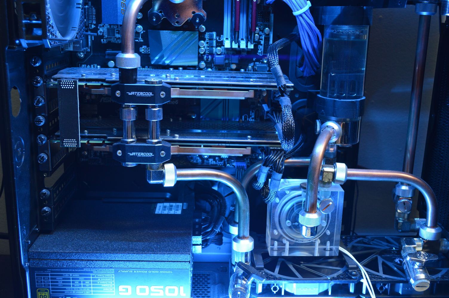
First, a couple shots of the system before I discuss the upcoming changes.
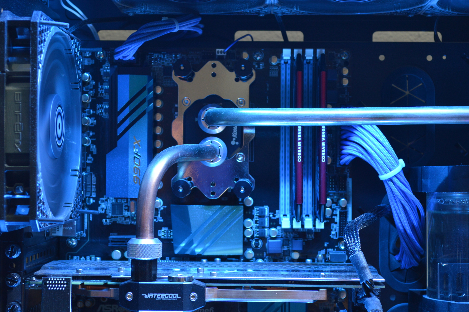
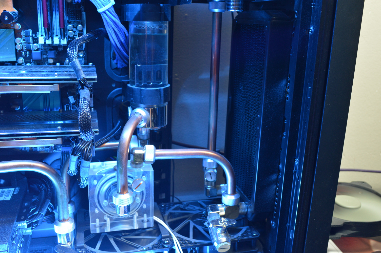
In the last picture, the fan to the right is cooling a dynamic voltage step-down regulator. It’s what I’m using to do the voltage testing mentioned at the start of this article. It’s also the reason the back isn’t on the machine.
The current hardline fitting count is almost two per component, including two on the pump and two on the reservoir. The graphics cards are in parallel, so there’s only one each there. So 14 hardline fittings total currently. With the pump and reservoir combined, I’ll only need two fittings there. But the three additional heatsinks will require six additional fittings. Plus the pass-through bracket will require four additional fittings. And there are 90-degree fittings to consider as well — some of the existing ones will be moved around.
Basically the loop will need to be redesigned as there are going to be major changes to the flow path of the loop to incorporate the additional components while also having to account for relocating the pump and reservoir to outside the case. If I was feeling really daring, I’d see about moving one or both of the 240mm radiators externally — perhaps later.
I already have a few ideas in mind for the flow as well. The pass-through bracket is a Koolance BKT-PCI-G. Right away the intake and outflow is basically decided without any additional guesswork. It’s just a matter of how to run the rest of it.
I’m not sure if I’m going to keep the graphics cards in parallel. I might do as demonstrated in the above linked Air 540 build and split them apart, letting one graphics card receive the inflow and the other graphics card be the last component on the loop before the outflow, or letting the southbridge cooler be the last component. In fact that’s not too bad of an idea — flow going from the inflow to the lower graphics card, through the radiators (bottom, front, then top), to the CPU block, VRMs, northbridge, top graphics card, then southbridge to the outflow.
Alternatively I can go from the northbridge to the southbridge, looping around the length of the first graphics card, which will allow me to take the outlet on the southbridge to the top graphics card, then to the outflow. The memory slots may get in the way of that idea, though. It’ll depend on how I can position the block.
There are three drain ports on β Ori., and that’s not changing. The drain port on the front radiator nearest the case window will be moved, though, likely to the outflow on the external part of the case. The drain design on this loop was made to allow for a drain port in the places where coolant was likely to get trapped trying to drain everything. Saying to have the drain “at the lowest point in the loop” doesn’t make much sense if coolant can get trapped and there isn’t much of a way to get the coolant moving.
The tubing going from the top radiator to the CPU block will be redone to give it a 45-degree bend off the 90-degree bend and eliminate the need for the extension fittings. As it is now, it’s not perfectly straight and may be impacting flow as a result — albeit not by much as the churning in the reservoir tells me it’s not a problem. It just doesn’t exactly look right.
So that’s basically it for now until the new blocks arrive. It’ll be interesting to see what I can do as far as overclocking is concerned after getting the blocks mounted and figuring out what fittings I’m going to need to make this happen.
You must be logged in to post a comment.