As you can probably tell, this hasn’t been a huge priority for me, given how many months it’s been since the last update. I haven’t given up on this project, though. Just had a lot of other things going on in the mean time while also figuring out what to do with this.
First, I’ve abandoned the IKEA SEKTION cabinet. And the loose rack rails. Part of the concern came with trying to make a frame with the loose rack rails to which the SEKTION cabinet would be attached. Loose rails are good for lightweight equipment cabinets: small network switches (unmanaged, not managed), patch panels, light audio equipment, etc. The latter point especially since the company that distributes the rails — Reliable Hardware Co. — sells other equipment and parts for audio producers, along with other small parts for making audio racks.
And while I was able to… mostly create a cabinet from these in the past, they’re not really suitable for my current goals. I don’t have the experience, space, and tools to make the frame I’d need.
Pre-built rack frame
So to eliminate that headache, I ordered a 15U open frame cabinet, 600mm (~24″) deep. What was delivered, not intentionally, was the adjustable-depth 15U cabinet — AR6X15-8001. Overall this means a cabinet a little larger than intended with a completely different structure than initially considered. Mostly.
Since previously I was planning to build a frame that would be enclosed inside an IKEA SEKTION kitchen cabinet. The difference here is I’m no longer building a frame for loose rack rails. This is, arguably, what I should’ve done from the outset.
Here’s the design of the open rack:
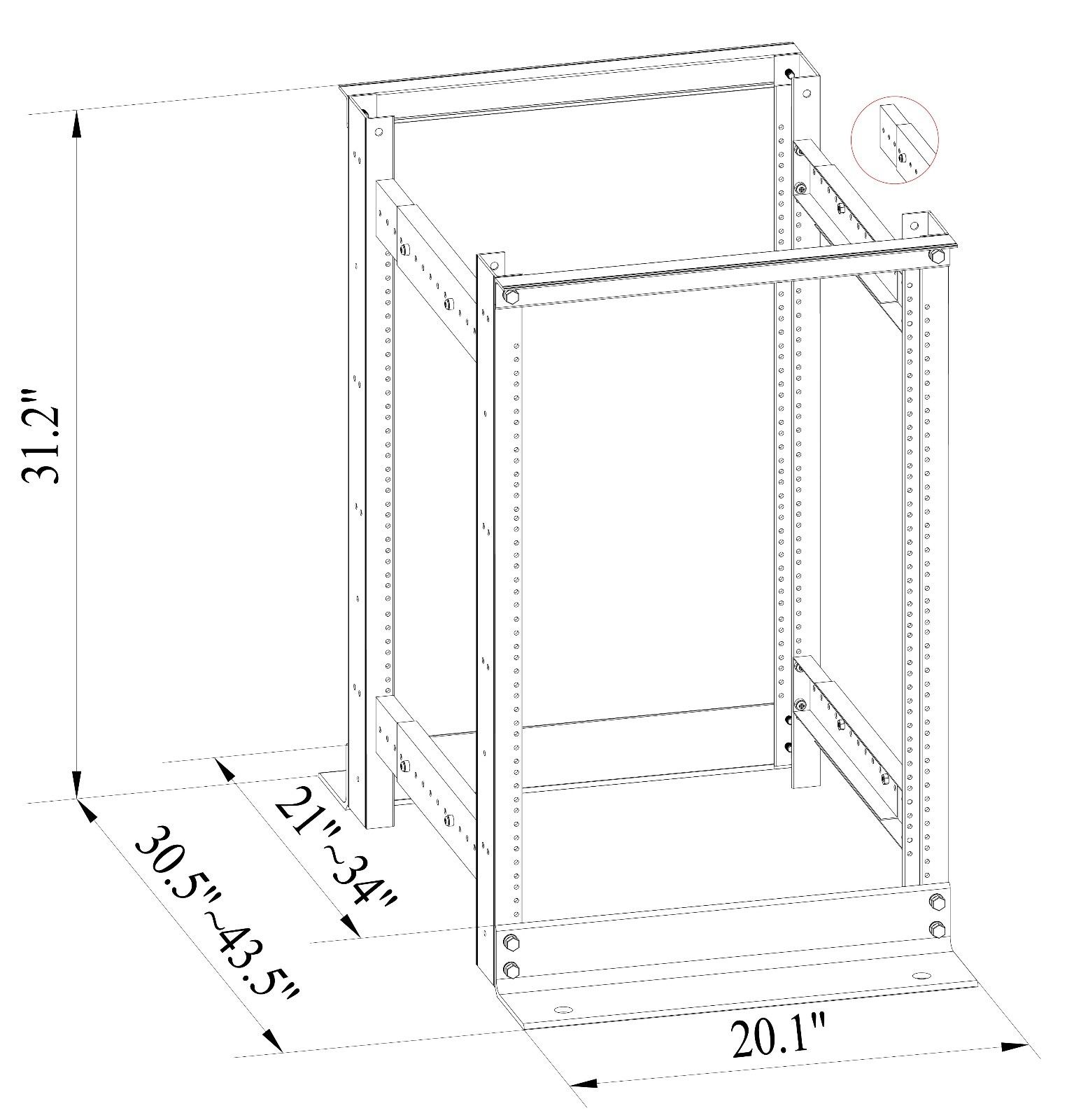
Here are the actual dimensions based on measurements:
- Width: 20.125″ (20-1/8″ or 511mm)
- Depth: 9.5″ (241mm) plus set depth adjustment for rack
- Height: 31.5″ (800mm)
The holes on the lower supports are 16″ apart, 8″ each direction off center. They’re 3/4″ diameter and 1-3/8″ from the leading edge. Intended for bolting the frame into concrete or a subfloor.
On the uprights you’ll also notice there are several sets of holes, though the drawing is misleading in how many are actually there. There are a pair of 5/8″ holes at the top, and a pair at the bottom, each 7/8″ in from the edge. And two 9/32″ holes down the middle. Useful for combining several frames together or building it into a table.
I have the frame assembled and have been using it to hold several servers along with my 10GbE switch. BUT… it won’t hold slide rails! The M6 threaded screw holes are the proper EIA-310 spacing, but there isn’t enough spacing between the corner posts to fit a standard-width server with standard slide rails. It has 17.5″ of clearance instead of the EIA-310 standard 17.75″ (450mm).
To hold the NAS and another server while finding a better option, I needed to use a rear-mounting kit.
So… Plan B.
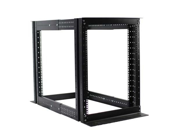
This one uses cage nuts. While that isn’t necessarily a guarantee that it’ll have the proper spacing between the corner posts, you can see quite easily that it’ll have plenty of room. Since the square holes for cage nuts have a standard sizing.
While listed as 15U usable height, the rack I received is actually 16U usable height, and the corner posts are 18U tall (31.5″ or 800mm). The top and bottom rack units are taken by cross brackets, which extend a little above and below the corners for a total height of about 32″ (813mm).
The top brackets extend about 1-3/8″ (35mm) from the uprights, so about 2.75″ (70mm) added to the depth at the top. The bottom brackets extend 4-7/8″ (124mm) out, so adding about 9.75″ (248mm) to the total depth. The frame is 21.25″ (540mm) wide. So for a 24″ depth, the frame will have a a 33.75″ x 21.25″ footprint (857mm x 540mm). This frame also keeps the two large-diameter holes in the bottom bracket for bolting into a floor.
Along the side of the corner posts are additional screw holes, one for each rack unit, similar to the mount holes on the loose rails I was initially going to use. This is useful if you plan to join multiple frames together. The corner posts are shy of 4″ deep.
So the question then is how to enclose it.
Enclosing the frame
Ging back to the forum post that inspired this, I’m going to use something as about a 2″ spacer, into which I’ll also be screwing down plywood to enclose the cabinet on the sides. The back will also be enclosed with ventilation out the top, similar to this:
except likely using PC case fans — either 80mm or 120mm — instead of the single 6″ fan in the video.
There aren’t great mounting holes for the front or back, so I’ll need to extend the side panels out far enough for a door on the front and the ventilation system on the back. That just leaves figuring out the bottom and top.
Top and bottom
The top isn’t going to be too difficult, since the cabinet will have a thick top to it to support whatever I decide to put on it: a computer or two, a monitor, but nothing too heavy. Maybe 100lbs at most that’ll be resting on the top supported by the metal frame. So about 1-1/2″ plywood (likely as face-glued 3/4″ ply with a ton of screws) should do the trick.
Same with the bottom, as references I’ve consulted said it should be able to hold the weight of a fully-loaded frame without a problem. Though to properly fit 1/2″ lag screws I’ve sourced locally, I may need to triple-layer the plywood sheets.
Overall dimension, currently, is looking to be about 36″x24″ footprint. The top and bottom will be attached directly to the frame.
So for now that’s the plan. Just a matter of getting into the hardware store and buying the plywood or laminated boards to make this happen. In the interim, I’ve got a few other projects going on, so who knows when I’ll be able to get there.
You must be logged in to post a comment.