- Radiator box for PC water cooling
- Mira
- Mira – II
- Mira – Finished
- Another pass by Mira
- Another pass by Mira – II
- Another pass by Mira – III
- Another pass by Mira – IV
- Another pass by Mira – V
- Some changes to the radiator box
- Back to AMD
- A more intelligent radiator box
- Upgrading the chassis
- My own Linux challenge
- Follow-up on my “Linux challenge”
Last I left this series, I mentioned a next step was making the radiator box smarter. The current iteration of the radiator box now includes intelligent control and monitoring of the fans and monitoring of the pump, liquid flow rate, and temperatures. I also removed the DDC pump and figured out how to get the D5 back into the system while also upgrading the power supply. Sounds like a lot went into this, doesn’t it?
First, here’s the current bill of materials (not including fittings, tubing, and wiring):
- Mountain Mods Pedestal (18″x18″x9″) with 9x120mm side panel1I had to special-request the 9x120mm side panel by placing an order for an 18×18 panel and adding in the order comment that I wanted the 9x120mm panel.
- 3x XSPC EX-360 triple-120mm radiators
- 9x Cougar CF-V12HB fans
- 3x Nanoxia Deep Silence 120mm 1300RPM fans2Appears to have been discontinued, 1500mm PWM is available
- Koolance PMP-450 D5 Vario pump
- AlphaCool HF D5 clear acrylic housing3The AlphaCool clear acrylic housing has since been discontinued
- 13x13mm M4 male-female vibration isolators
- Koolance INS-FM17N and ADT-FM03 (needed together)
- XS-PC G¼” temperature sensor plug
- EKWB EK-RES X3 250mm reservoir
- Singularity Computers4As of this writing, I continue to support Singularity Computers via their Patreon Ethereal Single (black)
- Mounting Rail 120
- Bulkhead fittings – 1x black (outflow), 1x silver (inflow)
- Koolance QD3-MSG4 (x1) and QD3-MSG4-BK (x1)
- NiuGuy Peculiarity 12V 8.5A (100W) power supply
- EAO Series 82 vandal-resistance switch
- C14 panel-mount plug
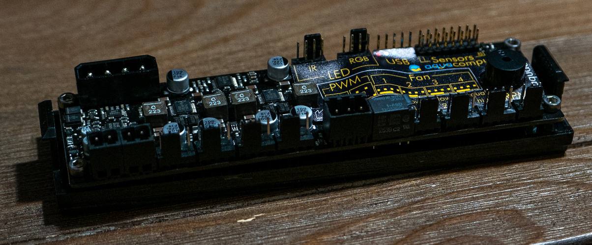
- Aquacomputer aquaero 6 LT
- SMAKN 12v to 5V/3A voltage regulator
And obviously you’ll need fittings, tubing, and wire. I used terminal blocks for helping with wiring all this up, so I’d recommend either that or bus bars. It just made things a hell of a lot easier.
Corsair Commander Pro
I mentioned a couple ways to approach this. Initially I went with the Corsair iCUE Commander Pro since it has temperature sensing (standard 10kΩ resistance sensor). The NZXT Grid+ doesn’t have that. Monitoring coolant temperature allows you to set up curves based on that coolant temperature.
I have two temperature sensors: one before the radiators and one after the radiators and before the reservoir. With the iCUE software, I could set up fan curves based on the coolant temperature. The rear fans – Nanoxia Deep Silence 120mm – would run at a near-constant, quiet RPM.
But there was one difficulty that I’d previously mentioned: it appeared to need all three voltages from the SATA power connector.
Or so I thought.
It will function without the 3.3V line. That voltage is likely required only if you’re planning to use LEDs.
Connecting to USB
Connecting this to my system, however, proved interested.
The USB connector on the Commander Pro is a 9-pin motherboard header connector, so I needed an adapter to turn that into two (2) Type A USB plugs, which could then be plugged into a USB hub to give one Type A plug. Which is where this comes in, the modDIY CAB138:
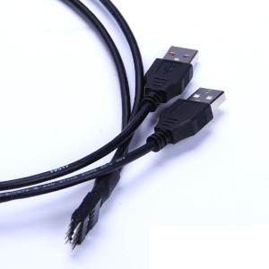
This turned the 9-pin header from the Commander Pro into two USB Type-A plugs. Then I used a USB hub to combine them. Probably could’ve gone with the version that gives a single Type-A plug, but I at least knew before I tried it that this would work.
Proof of concept
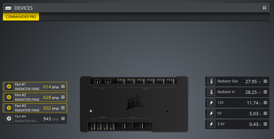
Before actually putting this into the radiator box, I needed a proof of concept to ensure it would still operate powered by a separate power supply than the main system. I connected the radiator fans to the first three (3) fan ports, and the rear fan trio to the fourth (4th) fan port. The two temperature sensors I plugged into the first two temperature sensor ports. I left the pump powered by the radiator box power supply. I used a separate power supply to power the Commander Pro.
And it worked beautifully.
But then it is a USB device, and I believe the USB standard requires devices to be able to work with a power supply separate from that of the system it’s plugged into if the entire device isn’t powered directly off the USB port – e.g. keyboard, mouse, and some external storage devices.
Back to the D5
I couldn’t get the PWM DDC to consistently run at full speed, or anything higher than minimum speed, for very long. So I decided to stop trying. The power supply I was using may have been part of the issue, but it was difficult to say for sure. And with having snipped off the plug to screw it into a terminal block, I couldn’t just plug it into another power supply to test.
So back to the D5, which is not PWM.
The vibration isolation mounts I had previously are 10x10mm M4 (from AlphaCool). And I ordered 13x13mm M4 vibration isolators instead. Couldn’t find the original mounts, and didn’t want to wait long for replacements.
Wiring everything up
While waiting for the new vibration isolation mounts to arrive, I drained the loop and tore down the box with the intent of wiring everything up. I did not cut the SATA plug off the Commander Pro – which turned out to be very fortunate.
I retained the terminal block, but cleaned up the wiring. The Commander Pro meant I could remove the voltage regulator I was using to lock the fans at 7V. In its place went another 4-circuit terminal block for wiring up a SATA connector to power the Commander Pro, with a step-down regulator connecting the 12V line to the 5V line.
Along with controlling the fans and watching the pump speed and coolant temperature, I also incorporated a flow monitor: Koolance INS-FM17N and the corresponding frequency adapter ADT-FM03, which converts the flow meter’s signal into an RPM signal. The Commander Pro, D5 pump, and flow meter all mean more power is needed for this as well.
I’d thought the 12V/5A power supply I bought for this was running borderline – though a Kill-A-Watt tells me otherwise – but then the DDC pump also wasn’t running at full speed or anywhere close. But to be on the safe side, I opted to upgrade the power supply to an 8.5A model, which also provided two (2) 12V outputs. This presented a slight challenge to the wiring.
With the previous iteration, the vandal-resistant switch – rated at 5A – was inline with the 12V circuit. And even then that wasn’t a great idea: you should always have headroom with electrical components, such as by not using a 5A rated switch on a circuit that could have 5A current flowing through it. Instead I should have always had it connected on the AC hot line.
And the prospect of current exceeding the switch’s rating left me with no choice this time. The switch is rated at 250VAC/5A, well above the rated current for the power supply, meaning it’s suitable to be used as a DC or AC switch up to the rated current.
Out with the Commander Pro
Not long after I completed the upgrades to the box, the Commander Pro started having… issues. Fan ports were dying off one by one. Port 2 died first, then port 1.
Doing some research, a bunch of forum posts I found said the Commander Pro has issues with fan splitters. Three-way splitters notably, which is how I had the fans connected: 12 fans in four (4) groups of three (3). Nothing in the manual or documentation says to not use splitters, or to not use three-way splitters. Indeed the manual implies they will work: max current per fan channel is 1A, 4.5A combined across all six (6) channels.
I have Cougar CF-V12HB fans on the radiators. The sticker on the back says 0.2A at 12V. The cross-flow fans are Nanoxia Deep Silence 120mm 1300RPM fans, which are rated at 0.16A. So well under 1A per channel – .48A for the Nanoxia group, and .6A for each group of the Cougar fans – and only about 2.3A combined for the fan channels. So what gives?
So out with the Commander Pro. The Grid+ V3 isn’t an option here as well since it supports at most 5W (0.4A) per channel, meaning only 1 or 2 fans. Plus it doesn’t have temperature monitoring.
So back to the drawing board. Along with filing a warranty replacement claim with Corsair.
Aquacomputer aquaero
This was about the only way I could see to get everything working optimally. My choice ultimately was the aquaero 6 LT or the aquaero 5 LT, with or without a Power Adjust 3.
The aquaero 5 and 6 both have only 4 fan channels. The aquaero 5 LT supports up to 1.65A per fan channel, while the aquaero 6 supports up to 2.5A. Either would make a good option for the radiator box. For the aquaero 5, I could split the nine (9) radiator fans between two fan channel. Fan controllers in the aquasuite can be set up for multiple outputs.
But having the fans split would mean a more complicated setup. Using the PowerAdust 3 would also mean a more complicated setup since I’d have to figure out how to run power to it. With the aquaero 6 LT, on the other hand, I could have all radiator fans on one channel using one of the NZXT Grid fan hubs I already have.
So ultimately I went with the aquaero 6 LT. Here’s how I have everything connected:
- Fan 1: Radiator fans
- Fan 2: Rear fans
- Fan 3: RPM sensor from pump
- Flow 1: Flow meter (calibration = 200 in aquasuite)
- Temp 1: Radiator out to reservoir
- Temp 2: Radiator in from system
- Temp 3: Internal air temperature sensor
Conflicting signals
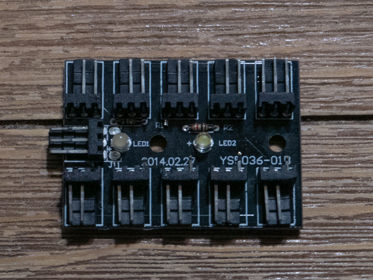
One… issue with some fan hubs and splitter cables: they don’t isolate the RPM signal to just one connection. The NZXT Grid was one, and the ModMyToys splitters also don’t isolate the fan signal to just one fan. That signal isolation is necessary or the competing signals will confuse whatever is reading it, meaning you won’t get an accurate RPM signal.
The PowerAdust 3 provides for that signal isolation without the need to modify it, meaning it’s the ideal out-of-the-box solution. Modifying one of the Grid hubs, however, was pretty simple: clip off the RPM signal pin from all but one of the plugs.
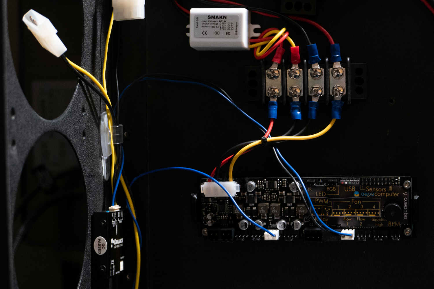
Rebuilding the radiator box
Rewiring the radiator box wasn’t difficult, though there was quite a bit that needed to be undone. I also took this as a chance to do what I should’ve done: move the power plugs for the fans to the other end of the radiator so they aren’t crowded against the rear fans, which has led to fans being inadvertently disconnected. Plus they reach the Grid while still being able to be tucked out of the way.
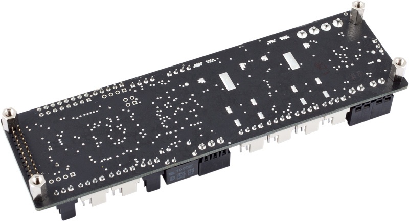
The aquaero LT is an aquaero XT without the LCD display. On the back of the device is a pin array that would connect to the screen and control panel – not sold separately from what I can find. The standoffs that are preinstalled allow clearance for those pins, but it complicates mounting it, since I can’t just put double-sided tape on the back of it.
The aquaero is designed to fit into a 5¼ drive bay, so a 5¼ drive bay cover from an old black chassis works out for this quite nicely. Just needed to drill holes for the screws. If you don’t have any of these lying around, you can buy them online for dirt cheap, or just use a strip of aluminum – which I nearly did till I realized this as an option.
I bought a sacrificial LP4 extension cable with a right-angle connector for powering this from the terminal block. The rest of the wiring was pretty straightforward. The pump and flow meter are powered from one of the 12V circuits, and the aquaero is powered from the other with the 12V to 5V regulator providing the 5V line.
Note: I put the aquaero on the radiator box wall before I started in on the power cable. Made it much easier to get near-exact lengths.
All fans are plugged into the fan control ports on the aquaero, with the pump RPM sensor plugged into Fan 3. The flow meter is plugged into the Flow 1 port. The flow rate that is displayed by aquasuite is 10x the actual approximate flow rate, though, as I can’t enter a calibration value high enough to compensate. I’d need to enter 2000 (1000 is the max allowed), so I have it set at 200.
For the time being, I have the USB cable for the aquaero plugged into the USB adapter and hub shown earlier. For the final USB connection, I want something that could be panel mounted so I don’t have a cable dangling out of it. I’ll figure that out later. That would be really the only change to this box that I would make aside from, perhaps, swapping out fans.
Performance
Since the time I finished the radiator box and published this article, I upgraded my system from the i7-5820k to the Ryzen 7 3700X with an X470 mainboard. The mainboard and CPU were the only components to be swapped out. So with the D5 pump back in the box and the fan curves configured, how is the performance?
For reference, the CPU is overclocked to 4.3GHz and the GPU is overclocked to +125 on the core, +500 on the memory through MSI Afterburner.
Running OCCT on “CPU: OCCT”, Test mode: “Small Data Set” with Furmark in the background at 1080p windowed, it took about 30 minutes for the coolant to reach equilibrium with the fan curves I had set, topping out a little north of 32.6°C (about 90.7°F) at the radiator inlet, a little under 31.5°C (about 88.7°F) at the radiator outlet (coolant going back to the reservoir), with the radiator fans at about 836rpm. (Note: the time showed on the OCCT test is after I had to restart it after an error).
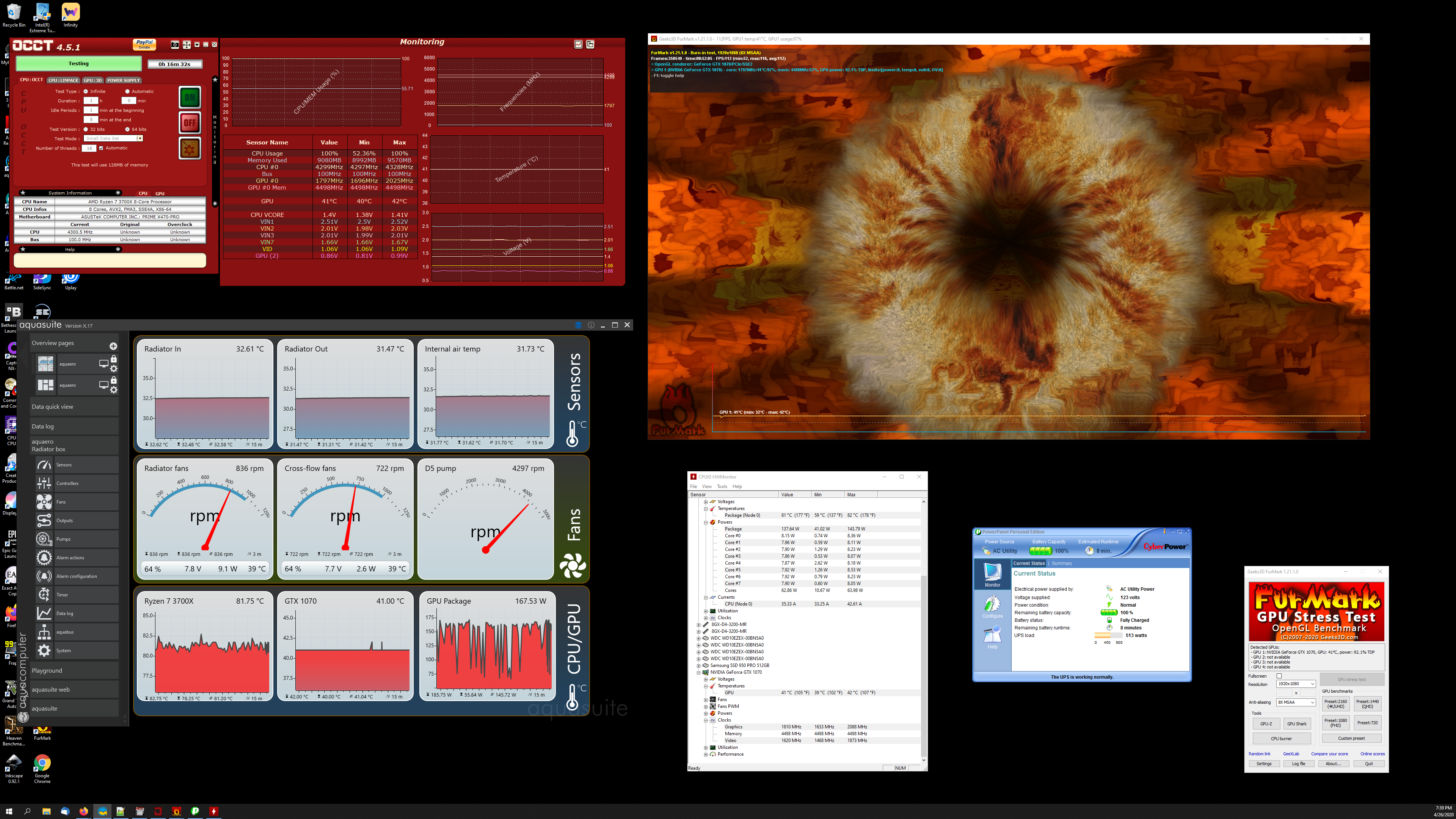
Click on the image to see it full-size. Word of caution: it’s a 4K screenshot.
As you can tell, the fans are well under 1000RPM, the general threshold for “silent” for even already-quiet fans, so there was no fan noise and virtually no pump noise as well. Any noise from this setup is coming from the fans in the NZXT H440, which I’ve been meaning to replace for a while and just haven’t gotten around to.
I added in the PowerPanel image to show how much power my entire system (including my dual 4K televisions) is drawing from the wall under load. It peaks at a little over 500W.
References
You must be logged in to post a comment.