As mentioned in a previous product review, the current ongoing project is attic insulation. Part of this project – and a significant source of delays – is rewiring.
First a little background. My home was built in 1951, making it older than my parents. And most of the insulation I’m removing is… original to the house. There was also a lot of wiring original to the house as well, meaning not grounded. According to what I could find, grounded wiring and outlets became required for new homes in 1974 when the updated electrical code went into effect.
So I’ve been replacing the non-grounded wiring as I found it. Along with splitting out the wiring so I don’t have… say, seven (yes, seven!) power lines coming to one junction box. (In all seriousness, if you think that’s a good idea, get some help.)
A lot of homes (most, I presume) have at least one 3-way switch pair. I have two, actually: the dining room and kitchen.
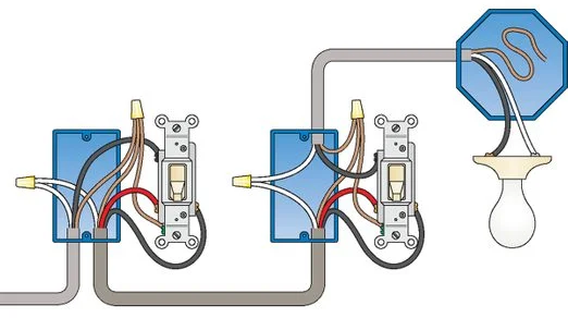
3-way switches need to be wired in series. And a lot of images and diagrams I’ve found show this. (Such as the one above, from The Family Handyman.) And I think it’s safe to say that most 3-way switches are wired like this. Which is all well and good, in theory. But the switches are typically on the opposite ends of a room, and wiring them directly in series means running two (2) power lines to each switch, one of them going between the switches, making things a bit… complicated.
And if you’re replacing older wiring (like me!), you probably want to avoid pulling two wires down through a wall. So is there a way to still connect the switches in series as needed that requires only one power line to each component?
Well you’re reading this, so the answer is obviously Yes.
Warning: I really shouldn’t have to say this, but I will anyway because people are stupid, and stupid people are litigious. Take any and all reasonable safety precautions when working with your house wiring. This means identifying and turning off the circuit breaker and using proper tools. These instructions are provided for informational purposes only, and you follow them at your own risk.
If you aren’t comfortable doing this on your own, why are you reading this article? Just call an electrician or a good friend who will do it for you in exchange for some beer.
Bill of materials
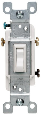
- 2 x grounded 3-way switches
- Light fixture
- 4″ square x 2-1/8″ deep junction box with raised ground and cover
- Fittings for the junction box
- Ground screw for the junction box
- 14/3 solid core with ground (rated for in-wall)
- Wire nuts or connectors (I used Ideal 32 In-Sure 2-port connectors)
Note: If you’re rewiring, make sure the switches you have are actually 3-way and not 2-pole switches and that both have a ground connector. If you’re unsure, or unsure about how old they are, just buy new 3-way switches from your local hardware store so you know you have a matched pair.
I had to do that as one of the two switches in the pair was a 2-pole, not a 3-way. Plus I have no idea how old they were.
Sanely wiring a 3-way switch
Step 1. Set the junction box and bring power to it.
The power delivery will be divided at the junction box. The power main will be coming to it, and the power to the light will be going away from the junction box with both switches being wired here as well. This will make your life so much easier than working inside a lighting fixture box.
Step 2. The light fixture.
The light fixture should be pretty straightforward. You’ll first want to wire the ground to the box. Then wire the light fixture according to its instructions.
Step 3. Wiring the switches.
A grounded 3-way switch has four (4) contacts: two brass, one black, and ground. The brass terminals are called “traveler terminals” and are used to connect the two switches together. The switch position determines which terminal power travels through.
Per the diagram above, if you were using separate power lines between the switches, you’d be using the red and black wires to connect them while passing through the white and ground. But here there is only one power line to the switch. That means you’ll be hijacking the white and red conductors for the “traveler terminals”. So connect separate lines to each switch as such:
- Ground to green
- Black to black
- Red and white to brass.
If you wire the brass terminals the same on both switches, they will need to be in the same position for the light to turn on. Wire them opposite each other, they will need to be in the opposite position for the light to turn on. Personal preference dictates what to do here. I personally have them wired the same just for the sake of simplicity.
Step 4. The junction box
Now to bring it all together.
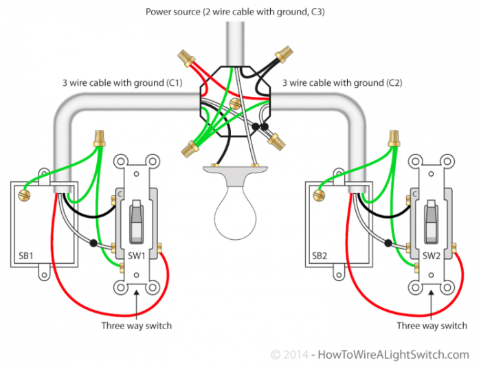
- White from the power main to white on the light fixture
- Red to red, white to white on the power lines going to the 3-way switches
- Black from the power main to black to one switch
- Black to the light fixture to black to the other switch
And obviously the grounds get connected together as well. If you used a junction box with ground lugs, per the bill of materials above, connect all the grounds there. Though you are talking about 4 grounds, so things could be a little tight.
In the end it should be something like this diagram (from the aptly-named HowtoWireALightSwitch.com), only using a separate junction box instead of the light fixture box as the central point:
Step 5. Enjoy
Don’t forget to close up the junction box and secure the switches. Just be sure to turn the breaker back OFF before doing so. Just in case.
You must be logged in to post a comment.