I’ve recently been getting into projects using LEDs. And one project is building a light using the YujiLED 100W COB. (Only available in pairs, it seems.)

And while you could just wire this up into a voltage step-up converter – which is a good way to at least make sure it isn’t DOA – that isn’t a good idea for long-term use. For that, you need to use a voltage regulator board that also has current limiting to prevent the LED from drawing too much current. Which could happen as the LED gets warmer.
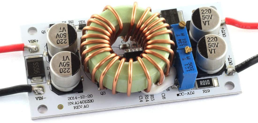
But the instructions for calibrating these boards tend to be… lackluster at best. So here’s the steps to actually do this right.
Warning: Before you begin this, mount the board to some kind of heatsink and fan. It will get very hot otherwise. Same with your LED.
- Turn the voltage trimmer pot all the way clockwise. You’ll hear a “click” with each full turn when you get to that point. This sets the lower limit on voltage.
- Turn the current trimmer pot all the way counter-clockwise. The “click” is a little less pronounced on this trimmer compared to the voltage trimmer pot. This sets the current limit well above what you’ll need for the LED.
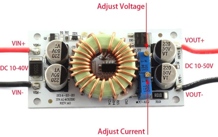
- Connect the board to the power source. Make sure to use a power source with an output voltage lower than the LED’s voltage range.
- Connect the board’s output to your LED through your multimeter with it set up to monitor current, or use an ammeter that can measure DC current (such as this one from Home Depot, which also has temperature probes, useful for measuring the temperatures to ensure you have adequate cooling).
- Turn on the power source. Depending on your power source, the LED should either be dimly lit or not lit at all.
- Turn the knob on the voltage trimmer pot counter-clockwise. This will bring the voltage up. If the light was off previously, it’ll eventually come on and start drawing current. But once the light starts drawing current, the current will start moving up fast, so take it slow at that point. Keep turning until the maximum rated current for the LED is reached – e.g. 3A in my instance.
- Turn the knob on the current trimmer pot clockwise until the current starts going down and the LED begins to dim. Then back off until you’re just a little under the rated current. I went to about 2.90A, which provides a little wiggle room for any fluctuations.
Using another multimeter or some other kind of voltage display (that supports the given range), check the voltage at the output of the LED driver board. It should be just inside the upper voltage limit for the LED according to its data sheet. In my instance, it settled at about 30.5V (31V is the upper limit), so pulling about 90W.
Now your voltage step-up board should be properly calibrated to your LED. With the upper current limit set, it should never draw more than a few milliamps above where it’s set. And attempting to turn the voltage trimmer pot higher will have no effect. Turning the voltage down, however, will dim the LED.
If you intend to have any kind of dimming, it’s best to use a PWM dimmer. Find one with a pulse rate of at least 10KHz to avoid interference with photography and videography. And make sure it’s rated for a high enough current and power for your LED and the requisite voltage.
And as noted above, in whatever final build you do with the LED and converter board, make sure you are adequately cooling the converter board along with the LED.
You must be logged in to post a comment.