- Putting older hardware to work
- Colony West Project
- Adding the GT 620
- Follow-up on ASRock BTC Pro and other options
- More proof of concept
- Adding a GTX 680 and water cooling
- Finalizing the graphics host
- ASRock BTC Pro Kit
- No cabinet, yet…
- Finally a cabinet!… frame
- Rack water cooling
- Rack water cooling, cont.
- Follow-up on Colony West
- Revisiting bottlenecking, or why most don’t use the term correctly
- Revisiting the colony
- Running Folding@Home headless on Fedora Server
- Rack 2U GPU compute node
- Volunteer distributed computing is important
Not long after publishing the last part to this series, I decided to test whether I could get four graphics cards recognized through the USB plugs. The fourth card is a Radeon X1650. And it was detected.

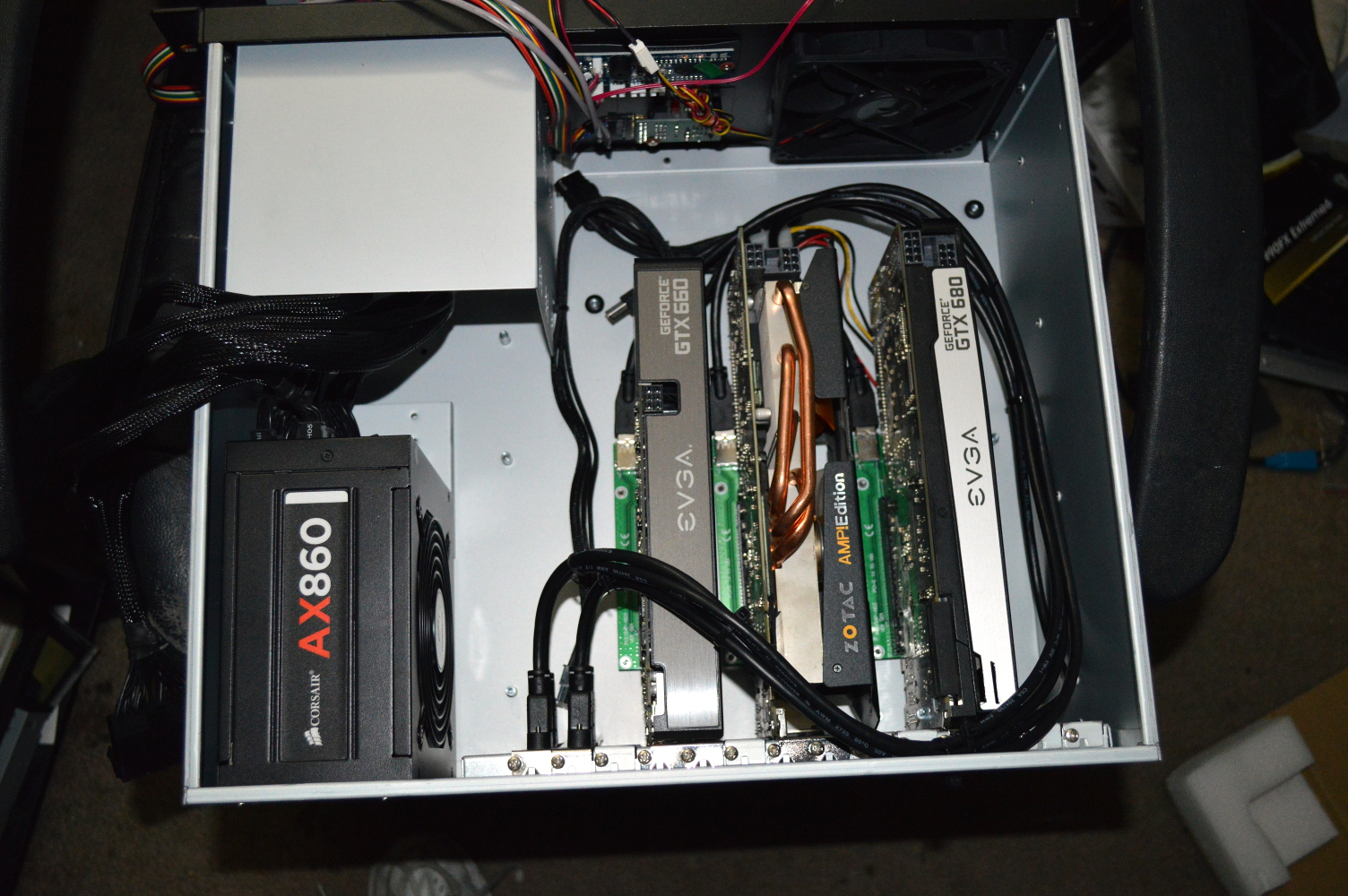
Four graphics cards: GT 620, GTX 660, Radeon X1650, and GTX 680. I could only leave it connected for a short while because the fan on this card is rather noisy — plus it can’t be used for Berkeley — but it was a good proof of concept. With that behind me, I ordered another GTX 680 off eBay — this time a Zotac GTX 680 2GB Amp! Edition (ZT-60102-10P, which EK’s Cooling Configurator confirms is a reference card). Interestingly the Zotac GTX 680 uses two 6-pin PCI-Express connectors instead of one 6-pin and one 8-pin like the EVGA.
But now things will get a little interesting, mainly because of the power connector requirements for all of these cards. The GTX 680s both take two power connectors while the GTX 660 takes only 1. Plus all 4 of the cards will still need to be powered by 4-pin Molex connectors. I think I’m going to need some more 3M Commander clips to keep things in order.
This is also where trying to power all of this might become an interesting problem and something I’ll need to keep in mind for the future. A while back I ordered a couple ATX breakout boards that were built for Bitcoin miners. This style of breakout is intended to be used with bare wire 6-pin PCI-Express connectors with all of the 12V lines lit to power mining hardware. And I’m thinking it can be similarly used to power graphics cards, when a few things are taken into account.
In a standard 6-pin PCI-Express connector, only 2 of the 12V lines are used (look at a dual 4-pin Molex to 6-pin PCI-Express dongle), even though in modern power supplies all three of the 12V lines will be lit — this is how a 6+2 connector is supported. On cards requiring an 8-pin connector, however, such as the EVGA GTX 680 in the setup, all 3 of the 12V lines must be lit.
For now, though, I’m going to rely just on the connectors on the power supply. There are enough to power two GTX 680s and two GTX 660s. The break-out board with the extra 6-pin PCI-Express connectors (with 8-pin adapters where necessary) will allow for connecting more than is typically supported since it’ll be drawing from other 12V connectors available on the power supply.
The only other thing I’ll need to figure out is just how to power it all on once it’s in the chassis, and there are a couple directions I can go with that.
Speaking of the chassis…
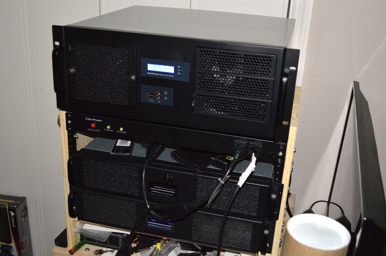
4U chassis for the graphics cards
I mentioned in an early article that the graphics cards would be going into a 4U chassis with a 14-slot rear panel. This kind of chassis is typically made for PICMG 1.3 backplanes and SBCs. I won’t go into detail on that other than to say it’s a very interesting topic. Some even support Intel “Haswell” processors.
But the existence of these chassis is great when you’ve got a lot of discrete hardware to support in some fashion. In this instance, it’s multiple graphics cards that need to be housed with USB connectors, powered, and, eventually, water cooled. Initially when I mentioned the chassis, I linked to an option by iStarUSA that was, frankly, ugly. Some searching around found other options, but in looking at PlinkUSA, I noticed that for some of their 4U chassis they have a 14-slot back plate for just $20, item 4U-14S-BP (I wonder what that stands for). So with that pretty much making up my mind, I ordered item IPC-G4380S, another “intelligent” chassis with a temperature display, with the optional 14-slot back plate.
Eventually I’ll order another fan mount bracket from Mountain Mods, but for now I’ll monitor temperatures with a single 120mm fan to see how well things work. I can always use double-sided tape to attach a second 120mm fan into the 5¼” drive bays if necessary.
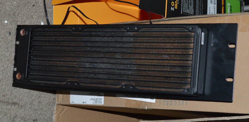
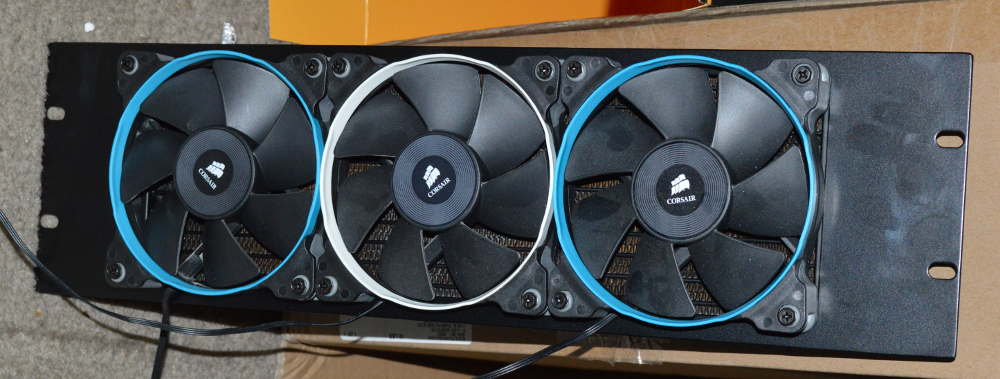
Radiator panels
The radiator panels arrived from the United Kingdom a little earlier than expected. And I picked up an EX360 radiator from my local Micro Center. The second radiator I’ll order from Performance-PCs along with another D5 pump when I’m actually ready to build out everything.
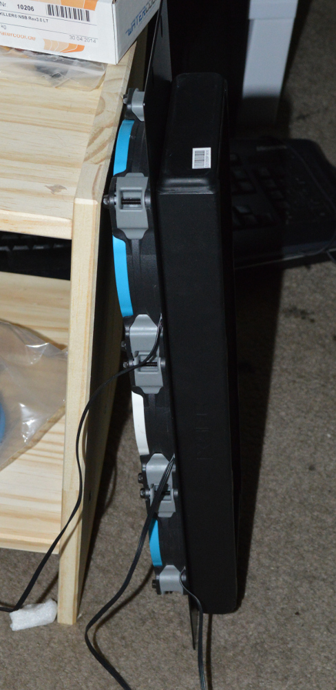
The panels do flex a little — they’re made of only 1.5mm steel with a lot of mass cut away — but sandwiching it between fans and the radiator makes it perfectly rigid. I’ll just need to figure out how to get the fan cables behind the panel for wiring up for power — either drill a hole through the panel or use a 1U panel between the radiators panels for that. I considered doing pull on these as well, but this configuration I think provides the best strength.
Boxing up the graphics cards
I’ll say up front that the 120mm fan that comes with this chassis will be getting replaced with something better. It comes with a Yate Loon 120mm fan — cheap and effective, but loud (rated at 28.8 dB/A), and I want quiet. And the 5¼” drive bays will get swapped out for another 120mm fan mount, or I might use double-sided tape to secure the fan.
The only thing I don’t like about PlinkUSA’s chassis is the fact they come with all of the bare panels covered in plastic. I understand why the do this, but I still reserve the right to voice complaint about it. It just reminds me of the aftermath of some really, really bad sunburns when I was 8.
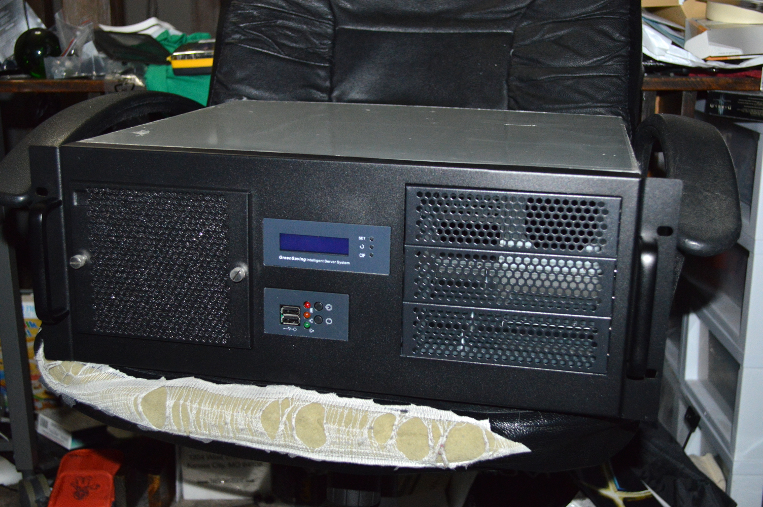
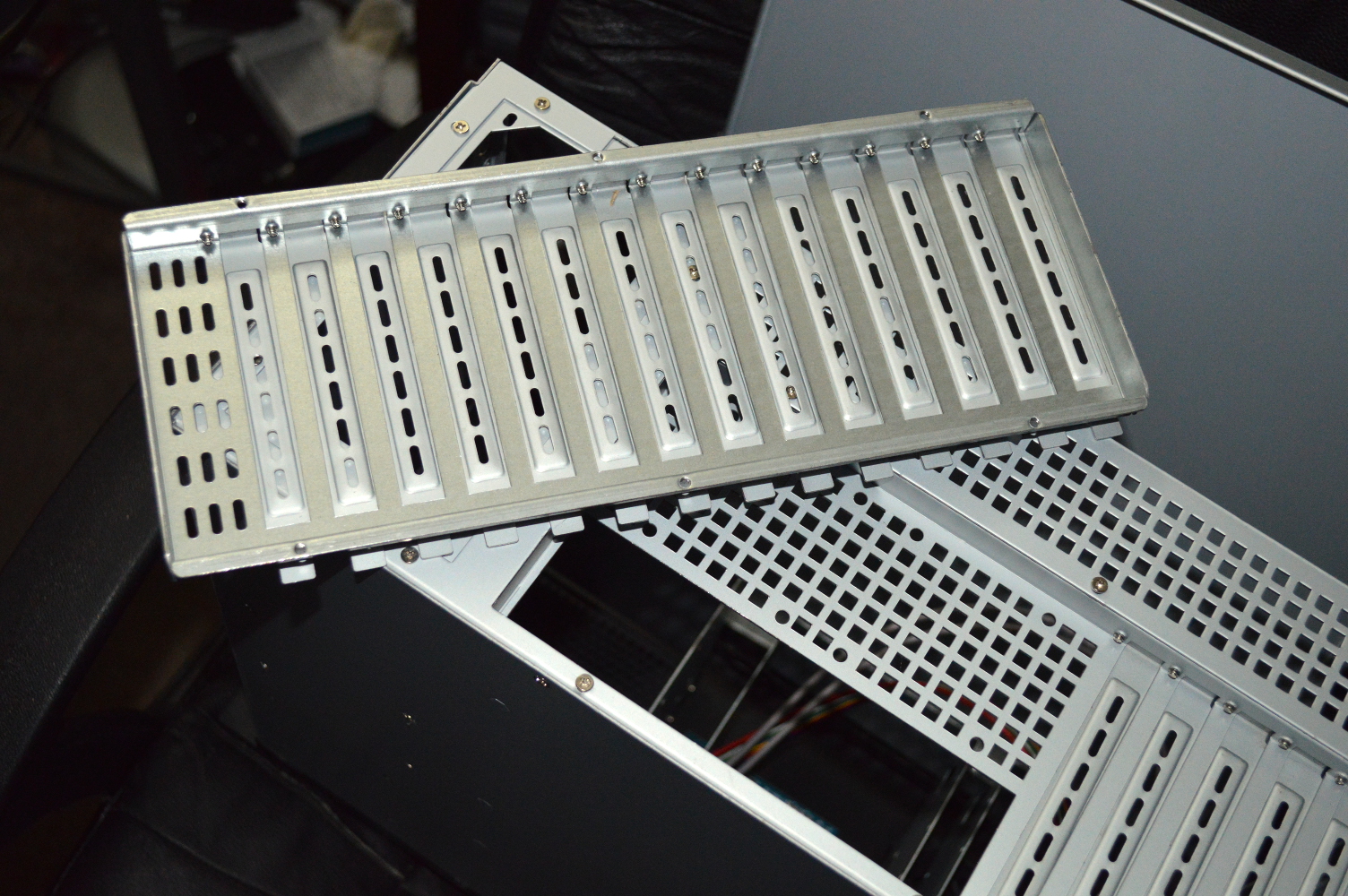
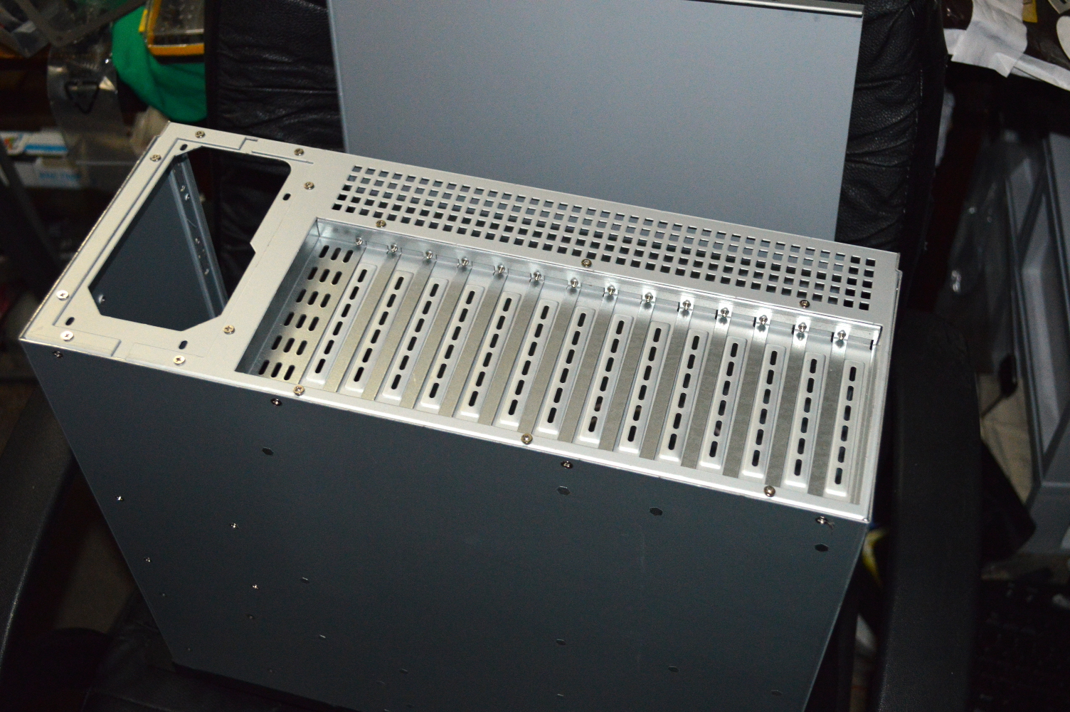
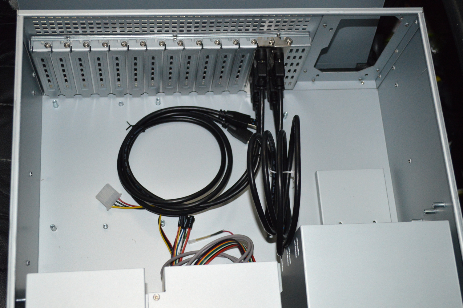
The 14-slot back plate was easy to install — just six screws at the back to take out the original ATX back plate and insert the 14-slot option. I assembled the USB panels as well. The USB 3.0 cables came from Cable Leader. I ordered the 3′ options on all of them because I’m considering mounting those above the graphics cards eventually instead of using back plates. That’ll depend on a couple factors, though.
Before I started preparing the case, I set the MilkyWay project to not load new tasks — it was the only one I had running right now — before disassembling everything. This is where the fun starts because the bottoms of the slot panels aren’t held in by anything. Only the screw will be securing the graphics card to the chassis, so I needed to think of something for securing the PCI-Express expansion board to the chassis as well so the graphics cards don’t go everywhere.
The Zotac card also gave me some cause for concern given the copper heat pipes that stick up off the top of it.
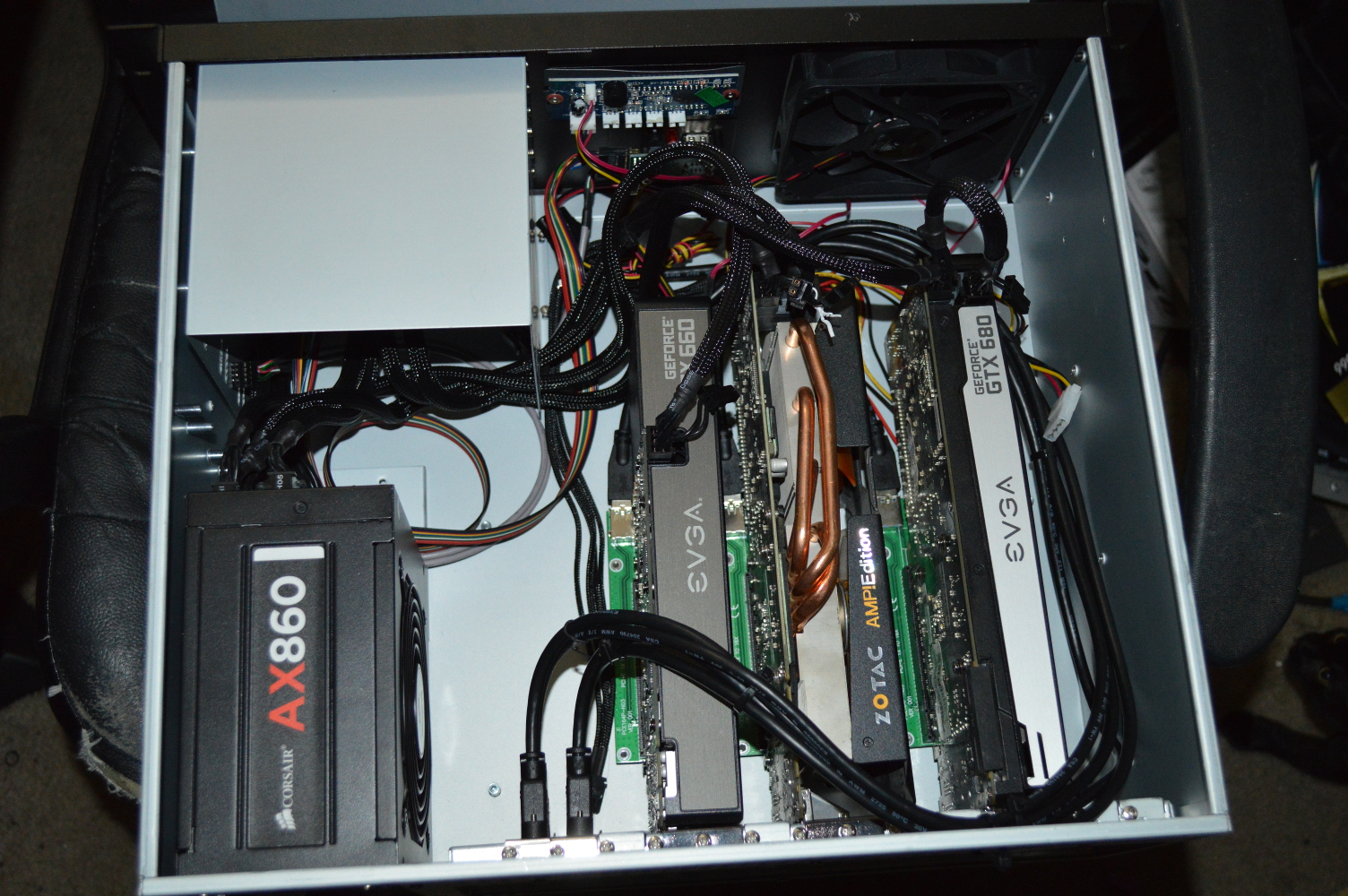
For powering this, I’m relying on a jumper plug on the 24-pin cable. I’m intending on using an Arduino Nano to try to use the case power switch to control the power supply — instructions for what I’m intending can be found over at Instructables.
As with the previous two systems, the fan controller on this isn’t connected to anything, but I’m still using the temperature sensor to show the internal temperature of the chassis — something rather important with these graphics cards. As was expected, the temperatures on the cards was higher than when they were exposed. I don’t know if a second fan would help that, or perhaps changing the installed 120mm to an SP120.
It’ll be interesting getting these hooked up for water cooling. At least going that route I can have the cards right next to each other instead of spaced out, so hopefully the system won’t look nearly as cramped. Some 3M Commander clips will help as well.
You must be logged in to post a comment.